Tuesday, 12 July 2016

poe thoughts and findings with Raspberry pi

I've used 2 splitters for this. One specifically sold to power Raspberry Pi, the other a more generic one, but it is cheaper and more flexible (it can output at 5V, 9V or 12V - obviously for direct power to a pi, it is on the 5V setting.

The switch in front is a Cisco SG200 08P, which is expensive, but provides close control and reporting on what is going on with each port. Much cheaper PoE switches (like the Netgear prosafe range) are available (but typically don't have the reporting I used here).

The ASIX AX88179 is the main part of a USB3 to Gigabit ethernet adapter. The Pi can drive significantly more than 100Mb with a Gigabit adapter (even although it is USB2). all the Gigabit USB adapters seem to be USB3 (quite sensible if you want to get close to full utilisation). Also being Gigabit means that potentially the green ethernet savings should kick in.

As a final test I had the Pi Zero running RPi cam control streaming live to a web browser on another PC, and with 2 servos waving the camera about. This took the power up to nearly 5 watts with everything running smoothly - apart from the live camera feed which was just a blur!

Conclusions

The TP-Link PoE adapter is the better solution - more flexible, more efficient AND cheaper.

The Official Rpi WiFi dongle seems to run at about 1/2 watt when idle.

The USB3 to Ethernet adapter I got is VERY inefficient - about 1 watt doing nothing.

You can run a pi very reliably this way - even with the camera and little servos running.

poe splitterloadpoe classpower (mW)current (mA)voltagegreen ethernetnetwork
RocksolITpi 3 idling419004247Nopi Ethernet
RocksolITpi 3halted48001747Nopi ethernet
TP-Link PoEpi 3 idling018004047Nopi ethernet
TP-Link PoEpi 3 halted07001547Nopi ethernet
TP-Link PoEpi 3 idling016003447Nonone
TP-Link PoEpi 3 idling025005447NoASIX AX88179
TP-Link PoEpi 0 idling012002647NoRPi wifi dongle
TP-Link PoEpi 0 halted0400947NoRPi wifi dongle
TP-Link PoEpi 0 idling010002247NoUSB3 - Gigabit no lan cable
TP-Link PoEpi 0 idling017003647YesUSB3 - Gigabit connected
TP-Link PoEpi 0 idling07001547Nono network adapter
RocksolITpi 0 idling413002847NoRPi wifi dongle
RocksolITpi 0 idling48001747Nono network adapter
TP-Link PoEpi 0 busy + servos046009047NoUSB3 - Gigabi

Monday, 11 July 2016

Making google cardboard work properly (with a web browser) part 2

Now I could set (and adjust) the lens spacing in my Google Cardboard, I needed a way to set up the spacing properly, but first.....

Rule 1: your display needs to have at least an 11cm wide viewable area - preferably a bit more. Without this width, significant areas of the image will only be visible to one eye - oh and I might need to adjust the app so it allows the panel to go off the edge of the screen.

To help with setup, I prepared a freestanding web page that enables settings to be tweaked, and saves those settings to local storage so they are persistent.

This web page can also be used as the base for display of stereogram images and similar things (like live streaming from stereo webcams), and can be run on devices that don't support the google cardboard app, so you can use google cardboard (the cardboard) without google cardboard (the app) - although not with any google api based apps obviously.

Now to getting the lens spacing properly setup. For me this means that:
  1. on first looking through the cardboard, the image should look right immediately - no waiting for the image to 'come together'
  2. shutting you eyes for for a few seconds and opening them again should likewise mean the image 'works' immediately
  3. The image should remain consistent across the whole field of view - no queasy feelings as you look towards the edges and corners of the view

web pages and other stuff.

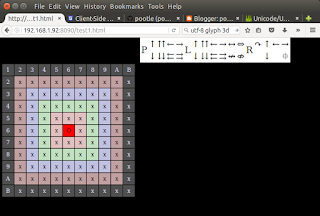
I wanted to make the little app as widely usable as possible - not just android - and to that end it is effectively a freestanding web page - here is a typical screenshot of the app in motion:

Below is the method I use to setup cardboard. The setup also prepares the settings for use in a stereo image viewer web page I am working on - more of that another day!

Note if you have a lazy eye or suffer from bouts of double vision or similar eye problems, you probably shouldn't do it this way!

Sunday, 10 July 2016

Making google cardboard work properly (with a web browser) part 1

First experiences with Google Cardboard were that things looked 3D, but it always felt a bit weird and uncomfortable. Usually the 'not rightness' got worse as I looked further from the centre of the image. To start with, I messed around with profile generator, but soon came to the conclusion I was starting from the wrong place.
Could I make it better?

Having worked out what I thought was the problem, the answer is yes, it can be made LOTS better (well it is for me anyway)

I decided that there are 2 main problems:
  1. because the lens spacing doesn't match my ipd, and the lenses have a fair bit of distortion, there is a small sweet spot and as I looked away from the sweet spot, the 2 views diverge in ways my brain did not like. This makes things feel more and more 'not right' as you move further from the centre.
  2. The lenses introduce a lot of pincushion distortion - I suspected that while not ideal, things would look a whole lot better if the spacing is fixed even with this distortion.
Of course having fixed item 1, a new profile should make the google app (and others that use the underlying cardboard API) look a whole lot better as well - after generating a new profile.

Google cardboard is set up for an ipd of around 64mm, and I measure my eyes at 67mm, but even this small difference seems to have a big effect.

So I set off a couple of days ago to:

  1. fix the ipd to lens mismatch.
  2. write an app (web page) that would allow me to view stereo pictures in a web browser.
and so our quest begins.... Part 1 is below, part 2 is here

Sunday, 3 July 2016

Pi Zero with steerable pi camera

I wondered how minimal I could go for a pi based camera, both in terms of size, power and to a lesser extent cost. I have been using webcams, but I soon found that even on a pi 3, 2 USB webcams wouldn't run reliably at more than very basic resolution under motion.

I decided to see how far I could go with a Pi Zero and a pi camera. Of course this means I can only put 1 camera on the Pi, but I gain flexibility in that the cameras are no longer USB cable length limited.

The result is very successful:

I also decided to I to try making the camera steerable using this little adafruit gadget.

Here is the final BOM:
  1. Raspberry Pi Zero with basic case and kit of leads
  2. Raspberry Pi Camera (mk 2)
  3. Raspberry Pi 2 Camera cable
  4. Adafruit mini pan tilt kit
  5. a few bits of wire
  6. 220uF & 100nF capacitors
  7. High power usb wart
  8. oh yes and a wifi or lan dongle
Total cost about £60 if you have to buy it all.

You will also need a usb hub for initial setup at least (I run mine with just the wifi dongle, so I don't need a hub)

The parts of this I was concerned about were:
  1. Were the servos and the pan tilt kit going to be stable / accurate enough?
  2. Would a single core processor cause glitching or other problems?
  3. Could I drive the servos from the Pi's 5v supply? (they draw about 250mA running, 600mA stalled and 10mA idling.)
  4.  Was there a reasonable way to route the ribbon cable?
 And the answers (so far):
  1. just about
  2. No, all looking good (using pigpio to drive the motors)
  3. Yes, adding the capacitors improved stability (of the motors - the Pi was fine)
  4. meh - ribbon cables are always a pain with 2 axis movement.
One arising questions:
  1. is it safe to run the 5v servo supply from pin 2?
Well on the Zero there is no fuse between the usb power socket and pins 2/4 so assuming your servos are well behaved, then yes. On other recent models the polyfuse has been uprated to 2A, so those should be fine as well.